
Part 4 LCD : Understanding TouchScreen (Without Library)
- Nov 9, 2021
- 4 min read
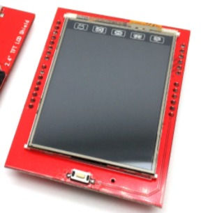
In this tutorial, we will be looking at touchscreen feature for the 2.4" TFT LCD Display.
To begin with, all that I have written here is just based on my experimentation and understanding. There is no clear article or datasheet that specifically discusses about touchscreen mechanism for 2.4" TFT LCD Display or it's controller. Due to that, the only way to find out how the touchscreen works is through experimentation.
Below is the code that I have written for my touchscreen experimentation.
//Touchscreen X and Y Connections
#define Y1 A3
#define X1 A2
#define Y2 9
#define X2 8

#define LCD_RD   A0 //Serves as read signal/MCU read data at the rising edge. Pg11 Datasheet
#define LCD_WR   A1 //Serves as write signal/command at the rising edge
#define LCD_RS   A2 //D/CX (0=Command/1=Data)
#define LCD_CS   A3 //Chip Select Pin : Active Low
#define LCD_RST  A4 //Shield Reset

void LCD_write(uint8_t d) {
  // Serves as write signal/command at the rising edge
  digitalWrite(LCD_WR, LOW); // WR 0

  // LCD Pins |7|6|5|4|3|2|1|0|
  // Uno Pins |7|6|5|4|3|2|9|8|

  //Arduino Port D : Pin 0 - 7, but Pin 0,1 not used in the LCD Shield
  //Arduino Port B : Pin 8 - 13,but Pin, 10,11,12,13 not used in the LCD Shield
  //Arduino Port C : Analog Pins

  PORTD = (PORTD & B00000011) | ((d) & B11111100);
  PORTB = (PORTB & B11111100) | ((d) & B00000011);

  digitalWrite(LCD_WR, HIGH); // WR 1
}

void LCD_command_write(uint8_t command) {
  // LCD_RS = 0, A2=0, D/CX (0=Command/1=Data) | DataSheet Page 11
  digitalWrite(LCD_RS, LOW);
  LCD_write(command);
}

void LCD_data_write(uint8_t data) {
  // LCD_RS = 1, A2=1, D/CX (0=Command/1=Data) | DataSheet Page 11
  digitalWrite(LCD_RS, HIGH);
  LCD_write(data);
}

void Lcd_Init(void) {
  //void does not return any value
  //void only execute instruction within it
  //similar to void setup and loop
  //This function will have LCD initialization measures
  //Only the necessary Commands are covered
  //Eventho there are so many more in DataSheet

  //Reset Signal is Active LOW
  digitalWrite(LCD_RST, HIGH);
  delay(5);
  digitalWrite(LCD_RST, LOW); //Actual Reset Done Here
  delay(15);
  digitalWrite(LCD_RST, HIGH);
  delay(15);

  //The below is just preparation for Write Cycle Seq
  digitalWrite(LCD_CS, HIGH); //Chip-Select Active Low Signal
  digitalWrite(LCD_WR, HIGH);
  digitalWrite(LCD_RD, HIGH);
  digitalWrite(LCD_CS, LOW);  //Chip-Select Active Low Signal

  LCD_command_write(0xC5);    //Test this Out | VCOM Control 1 : Colour Contrast Maybe
  LCD_data_write(0x54);       //VCOM H 1111111 0x7F
  LCD_data_write(0x00);       //VCOM L 0000000
  //LCD_data_write(B1010011);

  LCD_command_write(0x36);    //Memory Access Control | DataSheet Page 127
  LCD_data_write(0x48);       //Adjust this value to get right color and starting point of x and y
  //LCD_data_write(B0000100);     //Example

  LCD_command_write(0x3A);    //COLMOD: Pixel Format Set | DataSheet Page 134
  LCD_data_write(0x55);       //16 Bit RGB and MCU

  LCD_command_write(0x11);    //Sleep Out | DataSheet Page 245
  delay(10);                  //Necessary to wait 5msec before sending next command

  LCD_command_write(0x29);    //Display on.

  LCD_command_write(0x2c);    //Memory Write | DataSheet Page 245
}

int16_t row, rowdigital, col, coldigital;

void setup()
{
  Serial.begin(9600);
  Lcd_Init();
}

void loop() {

  pinMode(Y1, INPUT);
  pinMode(X1, OUTPUT);
  pinMode(X2, OUTPUT);
  //digitalWrite(X1, LOW);
  digitalWrite(X1, HIGH);
  digitalWrite(X2, LOW);
  row = analogRead(Y1);
  rowdigital = digitalRead(Y1);
  Serial.print(" DigitalRow : ");
  Serial.print(rowdigital);
  Serial.print(" Row : ");
  Serial.println(row);

//  pinMode(X1, INPUT);
//  pinMode(Y1, OUTPUT);
//  pinMode(Y2, OUTPUT);
//  digitalWrite(Y1, HIGH);  // Y variant B
//  digitalWrite(Y2, LOW);  // Y variant B
//  col = analogRead(X1);
//  coldigital = digitalRead(X1);
//  Serial.print(" DigitalCol : ");
//  Serial.print(coldigital);
//  Serial.print(" Col : ");
//  Serial.println(col);

}
In our first part of the code, we can see the touchscreen pins defined as below.
To be honest, the below pin configurations are what I found on the net. If you have the same or different LCD module, I would suggest you to test these pins to ensure that you have gotten the right pin for your LCD display. Without the right pin definition, this code will not work.
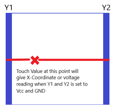
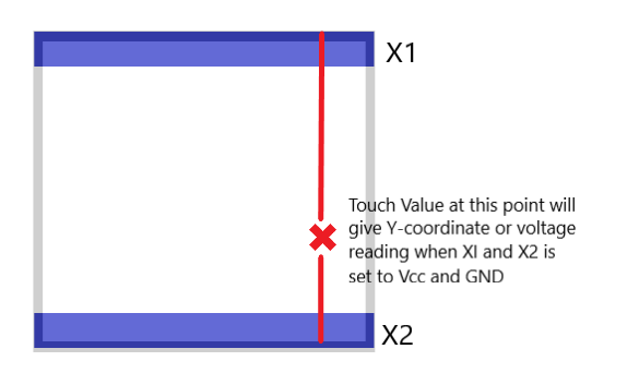
The above illustration shows how we can set the top and bottom film in LCD Display so that the x and y coordinates of a touch point can be detected by reading its voltage value.
The next part of the code contains void LCD_write, void LCD_command_write, void LCD_data_write and void Lcd_Init which has already been discussed in detail in previous LCD Display video tutorials.
  pinMode(Y1, INPUT);
  pinMode(X1, OUTPUT);
  pinMode(X2, OUTPUT);
  //digitalWrite(X1, LOW);
  digitalWrite(X1, HIGH);
  digitalWrite(X2, LOW);
  row = analogRead(Y1);
  rowdigital = digitalRead(Y1);
  Serial.print(" DigitalRow : ");
  Serial.print(rowdigital);
  Serial.print(" Row : ");
  Serial.println(row);
Within our void loop, we can see the above code. The above code simply sets 1 input and 2 output pins. The Output pins X1 and X2 is then set to HIGH and LOW respectively to emulate Vcc and GND. Once done, we perform analog and digital read to study the changes in voltage reading across the touchscreen area.
//  pinMode(X1, INPUT);
//  pinMode(Y1, OUTPUT);
//  pinMode(Y2, OUTPUT);
//  digitalWrite(Y1, HIGH);  // Y variant B
//  digitalWrite(Y2, LOW);  // Y variant B
//  col = analogRead(X1);
//  coldigital = digitalRead(X1);
//  Serial.print(" DigitalCol : ");
//  Serial.print(coldigital);
//  Serial.print(" Col : ");
//  Serial.println(col);
As you can see, the next part of the void loop is commented as in it would not be executed in Arduino. To enable this part, simply un-comment this part of the program. The reason why I have commented out this part of the program is so that we can clearly see the difference of values or voltage reading across Y and X axis or across rows and columns.
By understanding the voltage reading across the touchscreen, we can create program that will be making use of the behavior. For an example, to detect touch in a particular area on the touchscreen and subsequently perform an action such as lighting up a LED.
We have come to the end of our tutorial. I hope you've learned something thru this video. Please Don't Forget to Like and Subscribe.
For more detailed explanation, check out my YouTube video below.

Comments